Interactive Four-Bar Linkage Dynamic Force Analysis


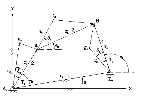
Given position, velocity, acceleration, and inertia properties such as mass and mass moment of inertia for each moving link of a four-bar linkage, we are able to perform force analysis for the linkage. Three static equilibrium equations, in terms of forces in the X and Y directions and moment about the center of gravity of the link, can be written for each link. The free body diagram is also available. For link 2, we get

F12x + F32x + Fg2x = 0      (1)
-m2g + F12y + F32y + Fg2y = 0   (2)
Ts + (-rg2) x F12 + (r2-rg2) x F32 + Tg2 = 0    (3)
where rg2=rg2*exp(i(theta2+delta2)) is the position vector from joint Ao to the center of gravity of link 2. F12 and F32 are the joint forces acting on link 2. Fg2 and Tg2 are the inertia force and inertia moment of link 2. m2 is the mass of link 2 and Ts is the driving torque. For link 3 we get
F23x + F43x + Fg3x = 0  (4)
-m3g + F23y + F43y + Fg3y = 0   (5)
(-rg3) x F23 + (r3-rg3) x F43 + Tg3 = 0 (6)
where rg3 = rg3*exp(i(theta3+delta3)) is the position vector from joint A to the center of gravity of link 3. F23 and F43 are the joint forces acting on link 3. Fg3 and Tg3 are the inertia force and inertia moment of link 3. m3 is the mass of link 3. For link 4 we get
F34x + F14x + Fg4x = 0      (7)
-m4g + F34y + F14y + Fg4y = 0   (8)
(-rg4) x F14 + (r4-rg4) x F34 + Tg4 + Tl = 0    (9)
where rg4=rg4*exp(i(theta4+delta4)) is the position vector from joint Bo to the center of gravity of link 4. F14 and F34 are the joint forces acting on link 4. Fg4 and Tg4 are the inertia force and inertia moment of link 4. m4 is the mass of link 4 and Tl is the torque of external load. Equations (3), (6), and (9) can be expressed as
Ts - rg2*cos(theta2+delta2)*F12y + rg2*sin(theta2+delta2)*F12x
+ [r2*cos(theta2) - rg2*cos(theta2+delta2)]*F32y - [r2*sin(theta2)
- rg2*cos(theta2+delta2)]*F32x + Tg2 = 0        (10)

-rg3*cos(theta3+delta3)*F23y + rg3*sin(theta3+delta3)*F23x
+ [r3*cos(theta3) - rg3*cos(theta3+delta3)]*F43y - [r3*sin(theta3)
- rg3*cos(theta3+delta3)]*F43x + Tg3 = 0        (11)

-rg4*cos(theta4+delta4)*F14y + rg4*sin(theta4+delta4)*F14x
+ [r4*cos(theta4) - rg4*cos(theta4+delta4)]*F34y - [r4*sin(theta4)
- rg4*cos(theta4+delta4)]*F34x + Tg4 + Tl = 0        (12)
Note that Fijx = -Fjix and Fijy = -Fjiy, equations (1-9) can be written as nine linear equations in terms of nine unknowns. They can be expressed in a symbolic form
Ax = b       (13)
where x = the transpose of (F12x, F12y, F23x, F23y, F34x, F34y, F14x, F14y, Ts) and is a vector consisting of the unknown forces and input torque, b = the transpose of (Fg2x, Fg2y-m2g, Tg2, Fg3x, Fg3y-m3g, Tg3, Fg4x, Fg4y-m4g, Tg4 + Tl) and is a vector that contains extenal load plus inertia forces and inertia torques.

The interface below allows the user to find the joint forces and the required input torque given the link lengths, theta1, one additional position, one angular velocity, one angular acceleration, the external load and the inertia properties for the mechanism.


Unit Type:
Link lengths (m or ft): r1: r2: r3: r4:

Link masses (kg or slugs): m2: m3: m4:

Link moments of inertia (kg-m^2 or lbf-ft-sec^2): ig2: ig3: ig4:

Position Vector for Center of Gravity

Magnitudes (m or ft): rg2: rg3: rg4:

Mode for all angles: theta1:

Select and input the known angle (theta2, theta3, or theta4):
value:

Departures from Link Positions: delta2: delta3: delta4:

External load (N-m or ft-lbf) on joint (1,4): tl:

Select and input the known angular velocity (omega2, omega3, or omega4):
value:

Select and input the known angular acceleration (alpha2, alpha3, or alpha4):
value:


Powered by Ch